
Guide for calibrating the laser field and red dot diode.
- Plug in the USB from the AP Fiber Cube to the Laptop.
- Plug in the silver USB supplied with the machine.
- Rename the folder to “EzCad2 AP-MOPA 110x110mm”.
- Launch the EzCad2 software located in the folder under “Software” for the 110x110mm lens.
- Once the software is launched, press FN-F3 to open the configuration parameters.
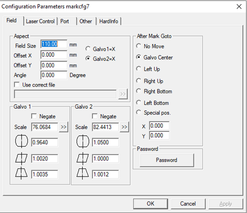
- Under the “Field” tab, change the “Field Size” to 110mm.
- Under the “Port” tab, configure the “Door IO” to “15 – Low”, “Marking Finish IO” to “4 – Low”, “Pulse Width” to “500”, and “Start Mark” to “14 – High” with “Pulse Mode” enabled. All other values should be null, and the settings should look like the settings in the figure below.

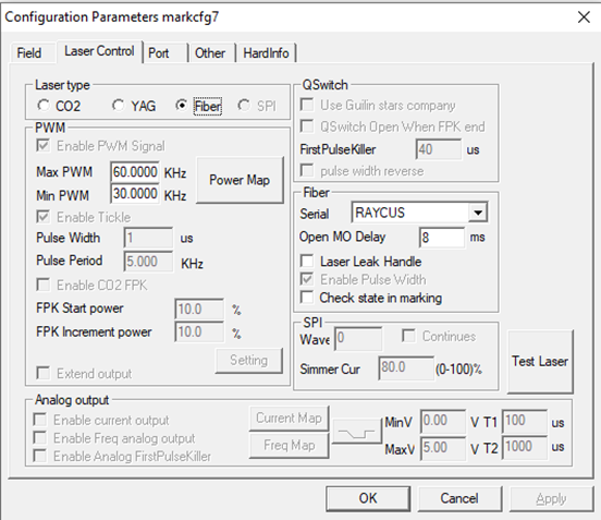
- Under the “Laser Control” tab, the parameters MUST be configured as the following and is dependent on the Laser Power Source installed in the machine.
For Raycus units the parameters are as follows:
Machine Model
Max Frequency
Min Frequency
AP-G30C (30 Watt)
60 KHz
30 KHz
AP-G50C (50 Watt)
100 KHz
50 Khz
For example, the AP-G30C Laser Control parameters should look as such.
- Exit the "Configuration Parameters" window, then click "Laser" --> "RotaryMark" from the Main Menu. You will be presented with the Rotary Mark Window.
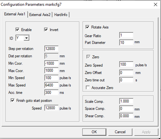
- Press FN-F3 to open the Param window. Under the “External Axis1” tab, make sure that “Enable” has a check next to it, and that “Invert” is also enabled.
- Set the ID to “Y” so that the Rotary is configured to the Y-Axis, and ensure that the parameters are configured as follows:
- Click “File” --> “System Parameter” to open the System Parameter window. Under “WorkSpace” set the sizing according to the image below for the 160mm Lens (110x110mm). Then press OK.

- Exit the software, and create a copy of the “EzCad2 AP-MOPA 110x110mm” folder, then rename the copy “EzCad2 AP-MOPA 175x175mm”.
- The USB is now set up to begin calibrating the two versions of the software.
CALIBRATING THE AP LAZER FIELD – 160mm Lens
- Install the 160mm Lens into the Fiber Cube if it is not already installed and launch the “EzCad2 AP-MOPA 110x110mm” software.
- Adjust the focal height for the material being marked using the 160mm Focal Stick.
- Press FN-F3 to open the “Configurations Parameter” window. Under the “Field” tab, change the Field Size to “110mm” then press OK.
- Begin the calibration process by first drawing a square matching the maximum marking region for the drawing. In this case 110x110mm for the 160mm Lens.

- Press F1 to turn on the red laser marking guide or press the Light button, then identify the shape.

- If distortion exists, then press F3 to open the Configuration Parameters menu and select the field tab.

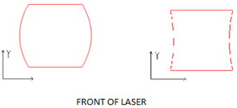
- Place a ruler along the Y-Axis, with the ruler inline with the corner of the object. If the lines of the square are curved, adjust the Directional Correction Coefficient.
Directional Correction Coefficient (Default 1.0, Range – 0.875-1.125).
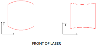
If marking is distorted in the Y-direction such as left image in the top figure below, increase the value of the parameter in the Galvo 1 section of the field. Subsequently, if the value is similar to the figure on the right decrease the parameter.
Galvo 1 (Y-Direction)
Once the Y-Axis is calibrated, place the ruler across the X-Axis, inline with the corners of the object.
If distortion is occurring in the X-direction, then perform the adjustment in the Galvo 2 section of the field.
Galvo 2 (X-Direction)
- If the marking guide appears to be slanted such as the marking in figure below adjust the Parallelogram Correction Coefficient (default 1.0, range – 0.875-1.125).

- At this point, marking lines should be straight with no curving. Lastly, check the Trapezoidal Correction Coefficient by measuring the length of the sides to ensure they are of the same length. If parallel lines are not of the same length, the marking will be trapezoidal distorted. Adjust the parameter until the lines are at the same length. at this point the square should only posses 90-degree angles, with all sides of equal length.
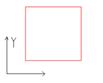
- Mark the square by clicking Mark (F2). Measure the length of each side of the marking to ensure that the marking matches the size given in the software. A 110x110mm square needs to measure 110x110mm after it is marked.
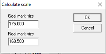
If the size of the object and the marking are not the same for the Y-Axis, click “>>” next to “Scale”, under the “Galvo 1” section of the “Field” tab. If the marking is not the same in the X-Axis, click “>>” next to “Scale”, under the “Galvo 2” section of the “Field” tab. You will be presented with the following window.

Enter a “Goal Mark Size” of 110mm, and enter the length of the marking for the respective axis into “Real Mark Size”.
Press OK, and the new marking scale will calculated automatically for the selected axis.
- Repeat marking and measure the object again, if the measurements are still not correct, repeat step 10, adjusting the “Real Mark Size”.
- Use the edge of the fiber stick to check for any curving of the lines. If curving exists, go back to step 5.
- The 160mm lens is now calibrated for the 110x110mm workspace.
CALIBRATING THE AP RED DOT– 160mm Lens
- After the lens has been calibrated, press FN-F1 to Frame the rectangle with the red dot. If they do not match go to the “Configuration Parameters” window, and click “Red Dot Pointer” under the “Other” tab.
The following window will open:

If the framing is smaller on one of the axis, increase the value of “Size Scale” for the axis.
If the framing is offset from the marking, adjust the “Offset Pos” for the axis.
Click “Ok” then Frame (FN-F1) the object again, repeat step 1 until the framing matches the calibrated rectangle.
CALIBRATING THE AP LAZER FIELD – 254mm Lens
- Close the software, and launch the copy of the software located in the “EzCad2 AP-MOPA 175x175mm” created earlier.
- Install the 254mm lens into the Fiber Cube.
- Adjust the focal height for the material being marked using the 254mm Fiber Stick.
- Click “File” --> “System Parameter” to open the System Parameter window. Under “WorkSpace” set the sizing according to the image below for the 254mm Lens (175x175mm). Then press OK.

- Press FN-F3 to open the “Configurations Parameter” window. Under the “Field” tab, change the Field Size to “175mm” then press OK.
- Begin the calibration process by first drawing a square matching the maximum marking region for the drawing. In this case 175x175mm for the 254mm Lens.

- Press F1 to turn on the red laser marking guide or press the Light button, then identify the shape.

- If distortion exists, then press F3 to open the Configuration Parameters menu and select the field tab.

- Place a ruler along the Y-Axis, with the ruler inline with the corner of the object. If the lines of the square are curved, adjust the Directional Correction Coefficient.
Directional Correction Coefficient (Default 1.0, Range – 0.875-1.125).
If marking is distorted in the Y-direction such as left image in figure below increase the value of the parameter in the Galvo 1 section of the field. Subsequently, if the value is similar to the figure on the right decrease the parameter.
Galvo 1 (Y-Direction)

Once the Y-Axis is calibrated, place the ruler across the X-Axis, inline with the corners of the object.
If distortion is occurring in the X-direction, then perform the adjustment in the Galvo 2 section of the field.
Galvo 2 (X-Direction)

- If the marking guide appears to be slanted such as the marking in figure below adjust the Parallelogram Correction Coefficient (default 1.0, range – 0.875-1.125).

- At this point, marking lines should be straight with no curving. Lastly, check the Trapezoidal Correction Coefficient by measuring the length of the sides to ensure they are of the same length. If parallel lines are not of the same length, the marking will be trapezoidal distorted. Adjust the parameter until the lines are at the same length. At this point the square should only posses 90-degree angles, with all sides of equal length.

- Mark the square by clicking Mark (F2). Measure the length of each side of the marking to ensure that the marking matches the size given in the software. A 175x175mm square needs to measure 175x175mm after it is marked.
If the size of the object and the marking are not the same for the Y-Axis, click “>>” next to “Scale”, under the “Galvo 1” section of the “Field” tab. If the marking is not the same in the X-Axis, click “>>” next to “Scale”, under the “Galvo 2” section of the “Field” tab. You will be presented with the following window.
Press OK, and the new marking scale will calculated automatically for the selected axis.
- Repeat marking and measure the object again, if the measurements are still not correct, repeat step 12, adjusting the “Real Mark Size”.
- Use the edge of the fiber stick to check for any curving of the lines. If curving exists, go back to step 7.
- The 254mm lens is now calibrated for the 175x175mm workspace.
CALIBRATING THE AP RED DOT – 254mm Lens
- After the lens has been calibrated, press FN-F1 to Frame the rectangle with the red dot. If they do not match go to the “Configuration Parameters” window, and click “Red Dot Pointer” under the “Other” tab.

The following window will open:If the framing is smaller on one of the axis, increase the value of “Size Scale” for the axis.
If the framing is offset from the marking, adjust the “Offset Pos” for the axis.
- Click “Ok” then Frame (FN-F1) the object again, repeat step 1 until the framing matches the calibrated rectangle.
Congratulations, the machine is now fully calibrated.