- Attach Gear head to stepper motor axial via set screws in gear. Be sure to align gear on axial with pre-attached gears on the Rotobuss.
- Attach 573S09 Stepper motor to Rotoboss via 4 machine screws. 3 of which attach via clearance hole and a lock nut. The 4th attaches to the belt tensioner, be sure belt tensioner is in correct orientation. (Figures 2 and 3)
- Attach belt to gears and tighten via belt tensioner and internal adjustment screw using #3 alien key.
- 573S09 Stepper motor comes with 6 wires. To wire to machine via existing connecter solder wires in following orientation.
- Solder the red and black wire leading from stepper to the black wire in connector.
- Solder blue and white wire leading from stepper to the blue wire in connector.
- Solder yellow and brown wire leading from stepper to the brown wire in connector.
- Reference wiring diagram below. (Fig. 1)
- Test rotary on machine to ensure correct direction of motion.
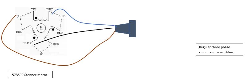
Figure 1: Wiring diagram
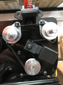
Figure 2: Rotoboss Large model, Belt orientation.
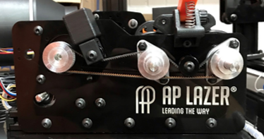
Figure 3: Rotoboss Junior, Belt orientation.