Rotary Multistep Driver DIP Switch Parameters
|
SW1 |
SW2 |
SW3 |
SW4 |
SW5 |
SW6 |
SW7 |
SW8 |
|
ON |
ON |
OFF |
OFF |
OFF |
ON |
OFF |
ON |
Table 1 – Rotary Multistep Driver DIP Switch Parameters (2 Phase)
Setting up the Rotary
Images imported to EzCad must be a .DWG file, as Bitmap files are not supported when using the rotary.
- Connect the rotary tool’s 4-pin connector to the port in the workspace located on the front of the machine.
- Fix the object to the chuck rotary, ensuring that the part is flush.
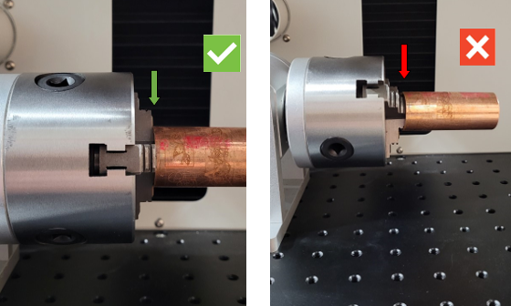
Fig. 1. – Rotary Part Alignment
- Adjust the angle of the chuck rotary so that the part is perpendicular to the lens of the fiber laser.
- Turn on the Light (F1) to ensure that the part is aligned in the desired position. The red dot guide should be centered on the object.
- Use the focal stick and the Up/Down switch on the left-side of the machine to calibrate the lasers focus.
Marking Text w/ Rotary:
- In EzCad, click “Laser” --> RotaryTextMark
- Define the diameter of the object, this is important to ensure that objects are marked with proper spacing and shape.
- Axis Step defines how far the rotary will rotate when Ctrl + Left/Right Arrow Key is pressed. This does not affect any actual marking, it is simply a tool for manually rotating and does not affect the origin (when marking is started, laser will return to the initial home position on the part).
- By default, the axis is set to Y and is inverted. If you wish to mount the rotary on the right-side of the workspace, then switch the axis to non-inverted by unchecking the “Invert” box.
- Turn on the Light (F1) to ensure that the text is in the proper position (RotaryTextMark will frame the position of the first character in the text).
- Begin marking by clicking Mark (F2).
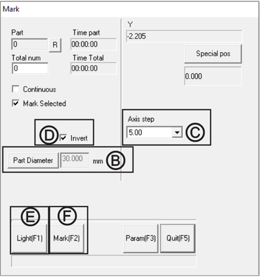
Fig. 2. – RotaryTextMark Parameters Window
Marking Image w/ Rotary:
Images marked with the rotary tool must be in .DXF format.
- In EzCad, click “Laser” --> RotaryMark
Marking By Split Size
-
- The “Expansion Axis” is preset to Y by default and should be inverted when rotary is placed on the left-side of the machine. If you wish to mount the rotary on the right-side, then switch the axis to non-inverted.
- Define the marking split size, this will determine the size of the marking region before the rotary moves. When engraving smaller objects, it is best to use a split size that is small to ensure the laser does not become out of focus on the curvature of the object.
- A split size of 0.05 or 0.10 works well for most objects as the interval is small enough to negate the distortion caused by the curvature.
- Note: Marking speed may be increased by increasing the split size, but too large of a split size can result in loss of focus.
- Ensure that “Force all split” and “Mark by split line” are not selected.
- Define the objects diameter by clicking on “Part Diameter” in the RotaryMark window/
- Turn on the Light (F1) to see the framing of the first split size, if split size is small the framing will appear as a line, rather than a box.
- Begin marking by pressing Mark (F2)
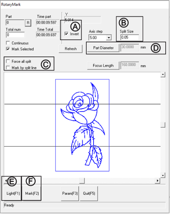
Fig. 3. – RotaryMark Parameters Window (Marking by Split Size)
Marking By Split Line
-
- The “Expansion Axis” is preset to Y by default and should be inverted when rotary is placed on the left-side of the machine. If you wish to mount the rotary on the right-side, then switch the axis to non-inverted.
- In the RotaryMark window, double click on the preview in locations you wish the rotary to split the engraving. A red dashed line will appear. The rotary will rotate each time a split line is reached.
Note: To remove a split line, right click it in the RotaryMark preview. - Ensure that “Mark by split line” and “Force all split” is selected.
- Define the objects diameter by clicking on “Part Diameter” in the RotaryMark window.
- Turn on the Light (F1) to see the framing of the first split location.
- Begin marking by pressing Mark (F2)
Note: Focus Length parameter does not need to be adjusted.
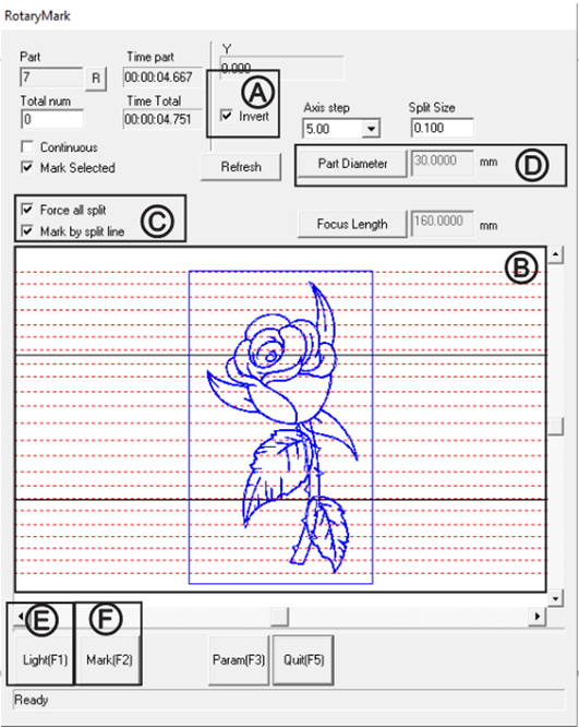
Fig. 3. – RotaryMark Parameters Window (Marking by Split Size)
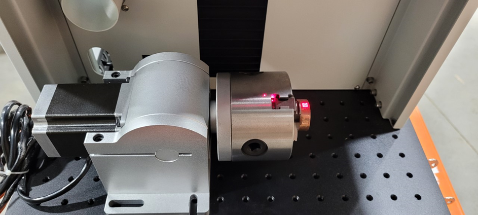
Fig. 4. – Rotary Apparatus